Project overview
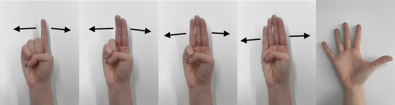
A device exploring a new approach to passwords: a smart-lock structure that uses machine learning to recognise gestures. Each small circular ring corresponds to the angle of a finger and is driven by its own servo. When all the gestures are correct, the lock opens.
A keypad password is something the user knows, which means anyone standing behind them can know it as well. This one is something the user performs, in the air, at a distance. The distinguishing information is not only which gesture is made but how far it is turned, so the password is four gestures each carrying a continuous angle, and all four have to land.
My contributions
- Connection and testing with Arduino
- Responsible for visual structure design
- Responsible for laser cutting
- Responsible for training the machine-learning model
Design point
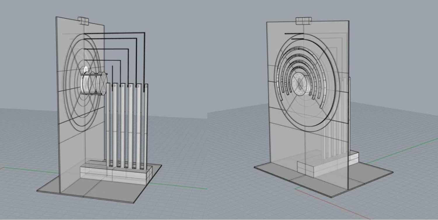
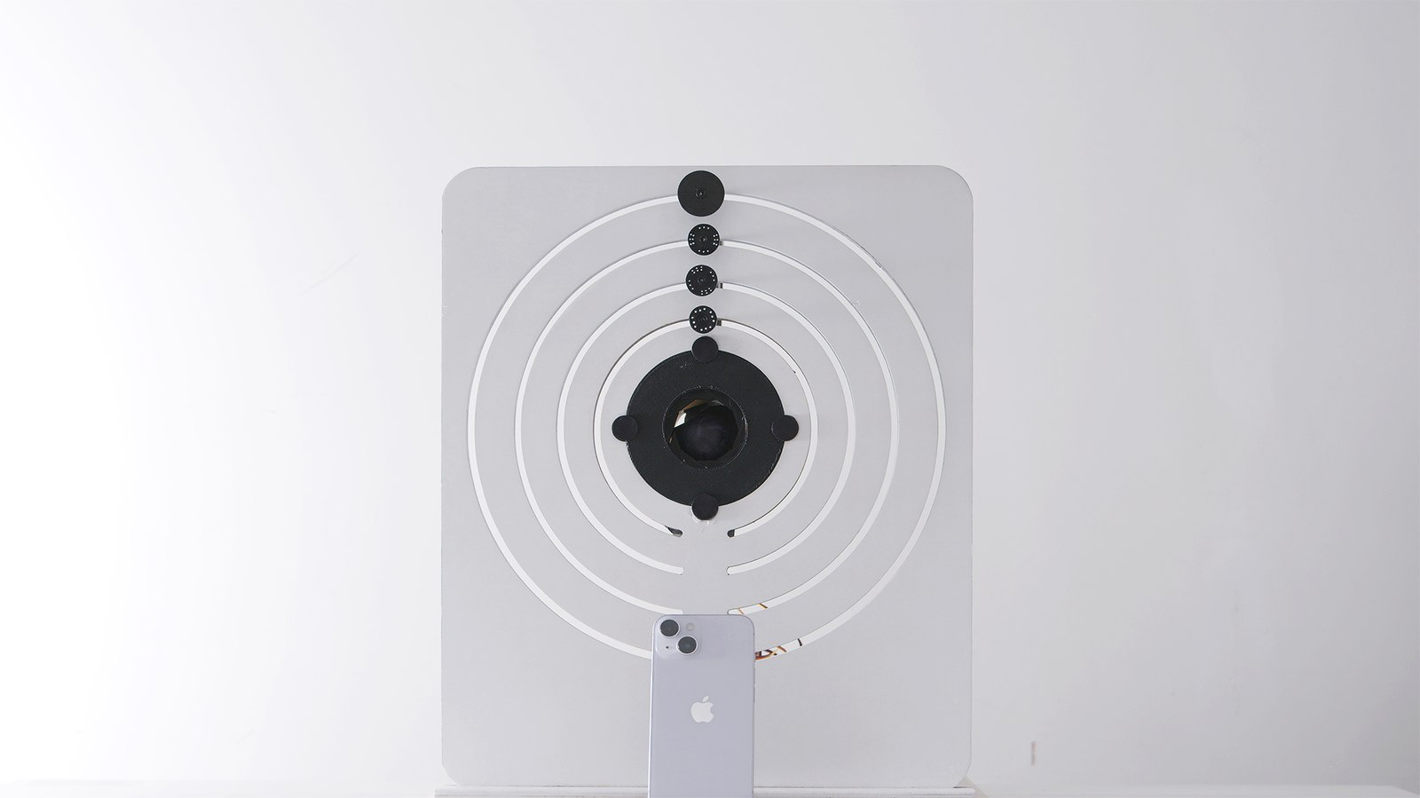
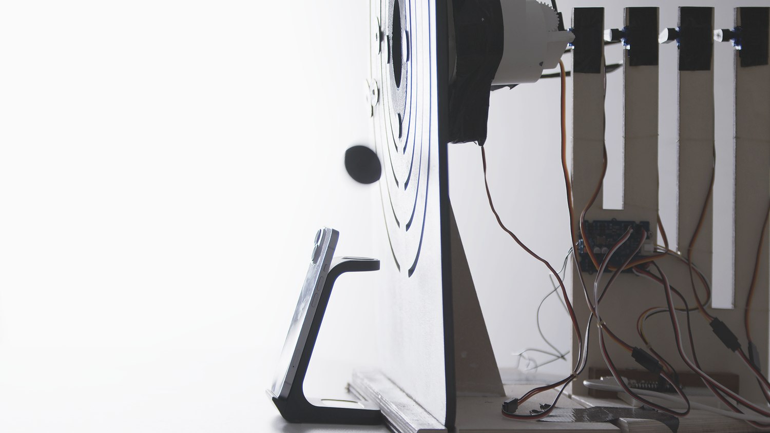
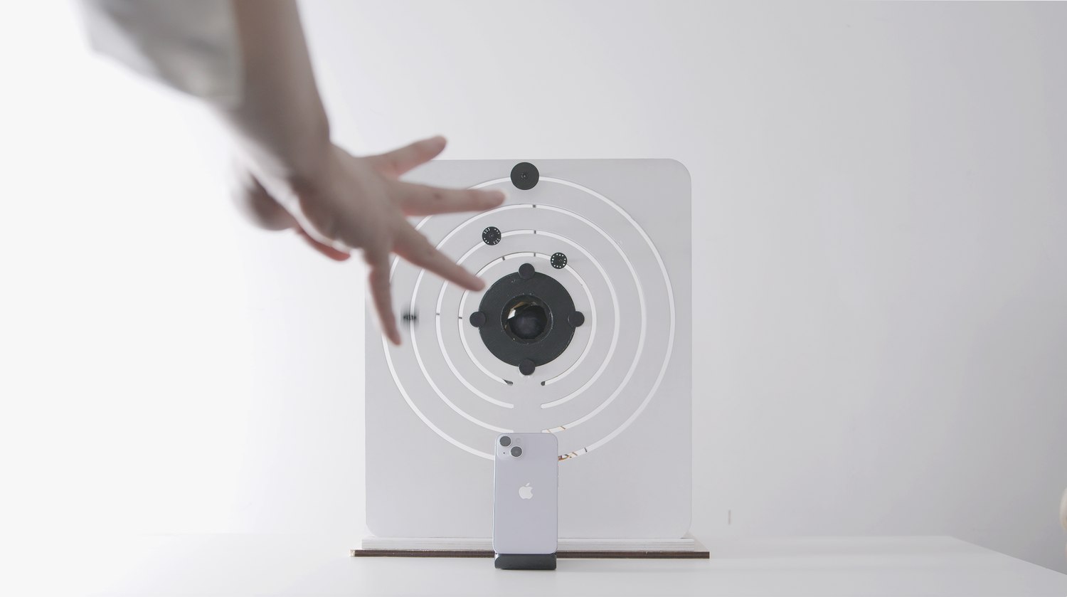
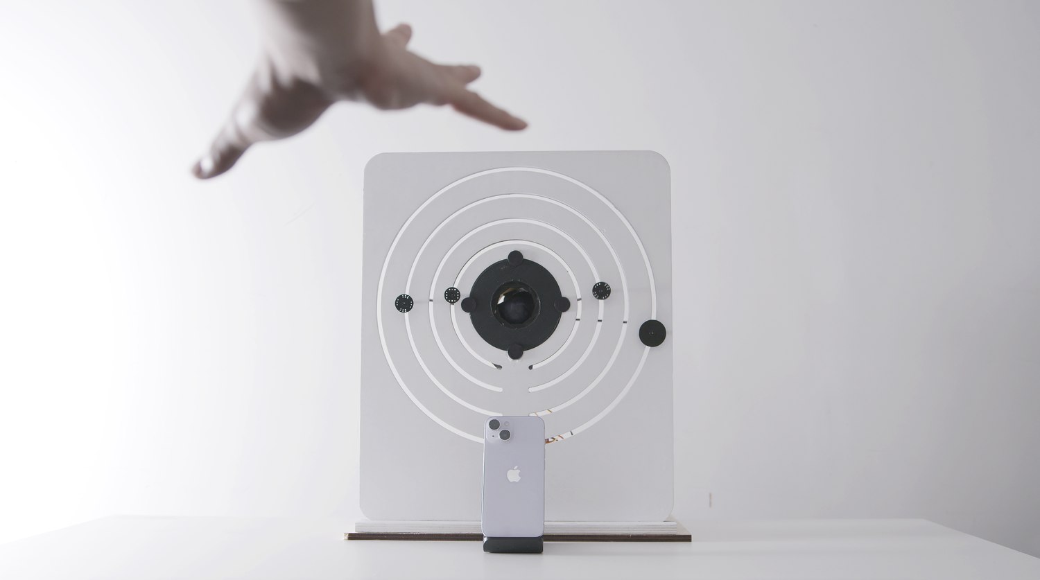
The design logic is that each gesture corresponds to a circle, and the rotation angle of the gesture controls the actual rotation of that circle. When all four gestures are rotated to their specified angle, the iris structure rotates open and the internal push rod pushes the locked item out.
The interface is the mechanism. No screen reports progress, because the ring is the readout: it tracks the user's hand continuously, so the distance still to travel is visible in the object itself and can be corrected in real time.
Technical implementation
The signal chain
Four tools, five stages, one continuous path from a hand in the air to a servo horn holding a specific number of degrees.
 01
01
 02
02
 03
03
 04
04
Stage three is where the lock gets its resolution. A single classifier would have produced a device with four states. Running classification and regression on the same input stream gives every gesture a continuous value alongside its identity, so the password space is four gestures multiplied by an angle rather than four gestures alone.
Hardware
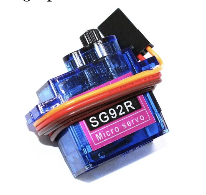
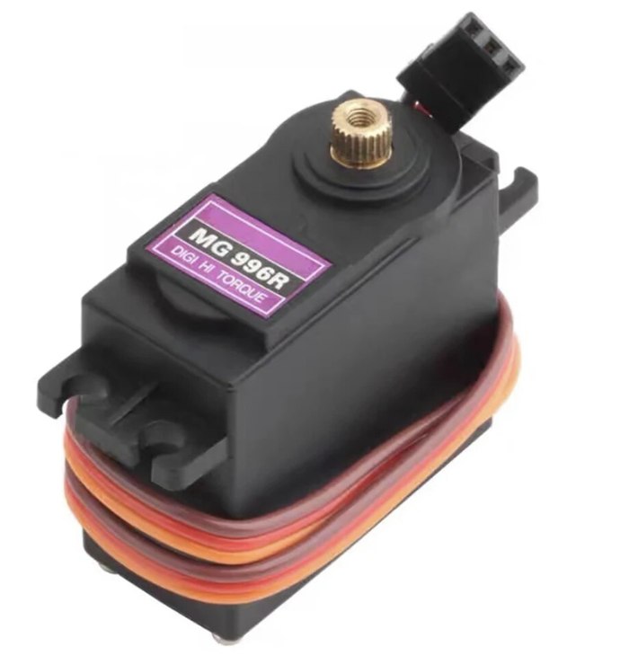
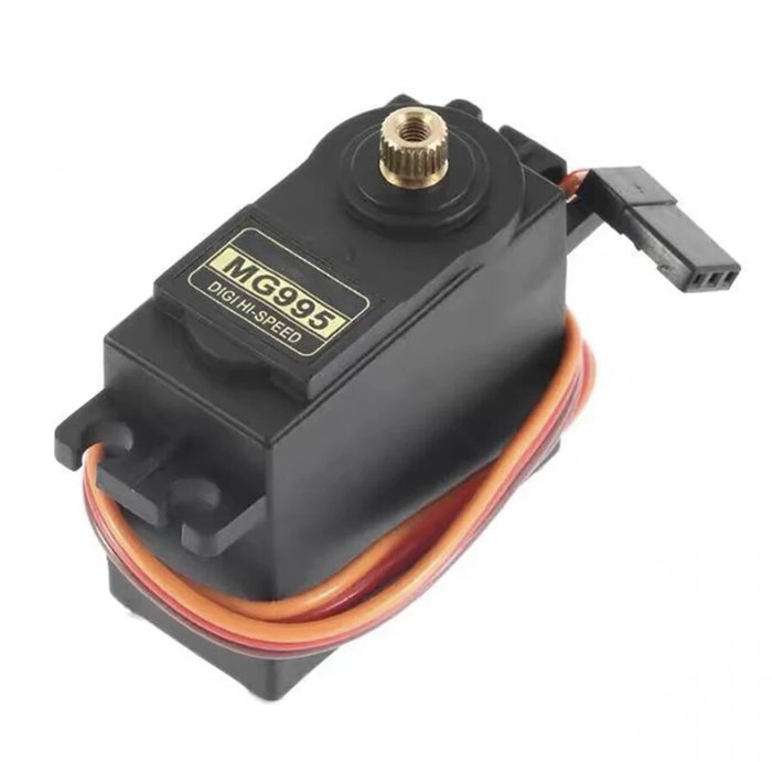
The device consists of four SG92R micro servos, one MG996R servo, one MG995R servo, and an Arduino, addressed through a PCA9685 driver.
The wire protocol
Wekinator emits a new prediction many times a second, and the microcontroller has to act on each one without ever getting confused about where a message starts. The format that solves this is deliberately the dumbest one available: a fixed four-byte frame, no delimiters, no handshake, nothing to parse.
Fixed width is what makes Serial.available() >= 4 a sufficient test for a complete message. Zero-padding removes the only ambiguity a variable-length angle would introduce, so the firmware never has to look for a terminator, never blocks waiting for one, and cannot desynchronise from a dropped byte for longer than a single frame.
Three decisions behind the firmware
- The door latches, the rings don't. Predictions arrive continuously, so the open sequence is guarded by a state flag. Without it the mechanism would re-trigger on every frame that still matched the final gesture, and the iris would grind against its own end stop.
- An angle range, not an exact value. A model reading a human hand will never return the same number twice, so a ring counts as correct anywhere inside a valid band rather than at a single degree. The band is what makes the lock openable by a person instead of only by a recording.
- A PCA9685 driver instead of direct pins. Six servos exceed what an Arduino can drive cleanly on its own timers, and stalling servos pull the board's rail down mid-move. Moving PWM generation and power off the microcontroller is what stopped the rings jittering when more than two moved at once.
Firmware sketch, in full
#include "PCA9685.h"
#include <Wire.h>
ServoDriver servo;
const int servoR1Pin = 1;
const int servoR2Pin = 2;
const int servoR3Pin = 3;
const int servoR4Pin = 4;
const int servoDoorPin = 5;
const int servoR6Pin = 6;
const int minValidAngle = 20;
const int maxValidAngle = 180;

void setup() {
  Wire.begin();
  Serial.begin(9600);
  servo.init(0x7f);
}

void loop() {
  static bool servoDoorMoved = false;
  if (Serial.available() >= 4) {
    char classification = Serial.read();
    int angle = 0;
    for (int i = 0; i < 3; i++) {
      char digit = Serial.read();
      if (digit >= '0' && digit <= '9') angle = angle * 10 + (digit - '0');
    }
    switch (classification) {
      case '1': servo.setAngle(servoR1Pin, angle); break;
      case '2': servo.setAngle(servoR2Pin, angle); break;
      case '3': servo.setAngle(servoR3Pin, angle); break;
      case '4': servo.setAngle(servoR4Pin, angle); break;
      case '5':
        if (!servoDoorMoved) {
          // open once, then latch: predictions keep arriving after the
          // sequence completes and the iris must not be driven again
          servo.setAngle(servoDoorPin, 180);
          delay(5000);
          servo.setAngle(servoR6Pin, 179);
          delay(2000);
          servo.setAngle(servoR6Pin, 90);
          servoDoorMoved = true;
        }
        break;
    }
  }
}
Structure
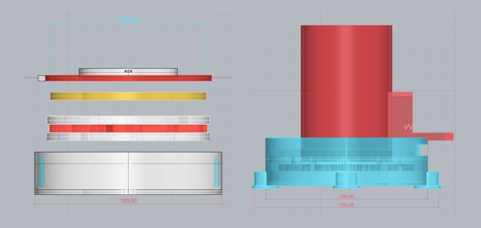
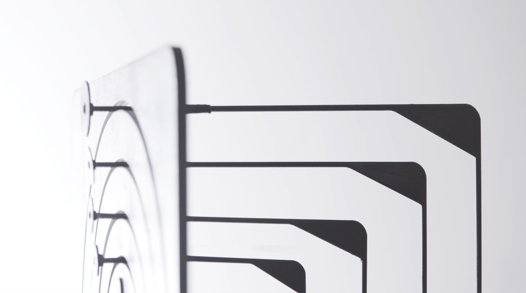
The mechanism was drawn, sectioned and laser cut, then assembled around the servo positions.
In use
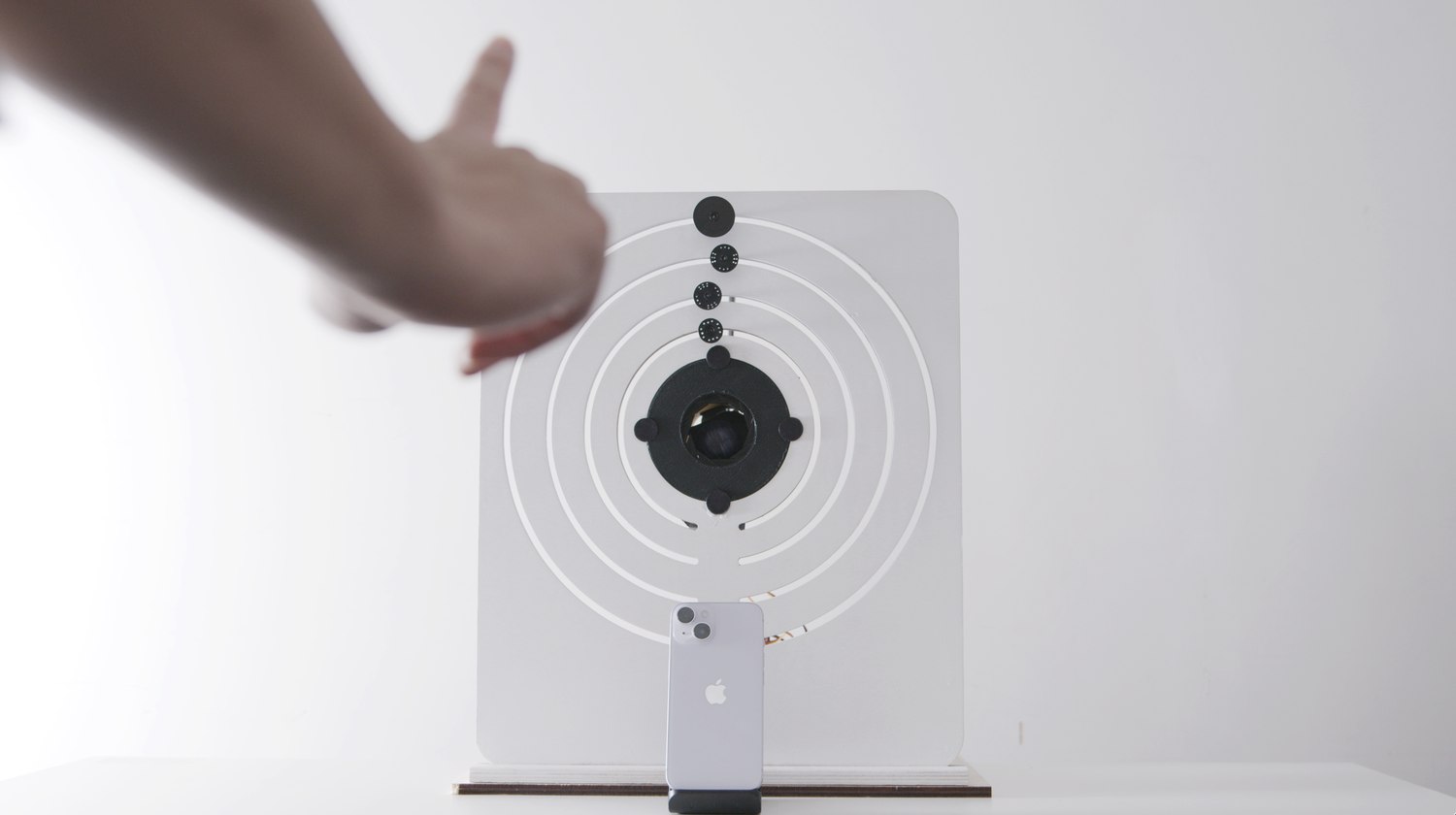
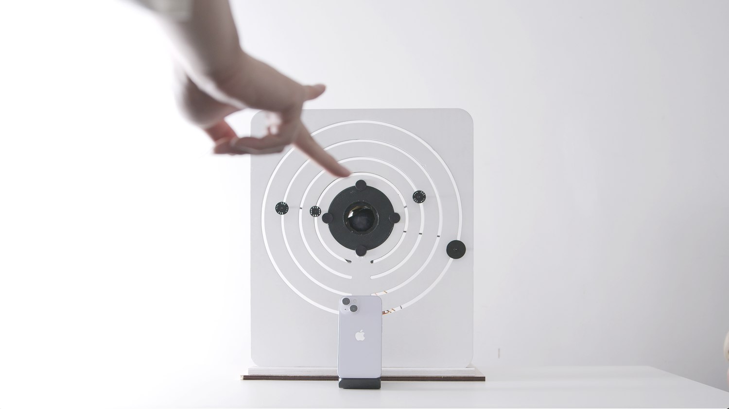
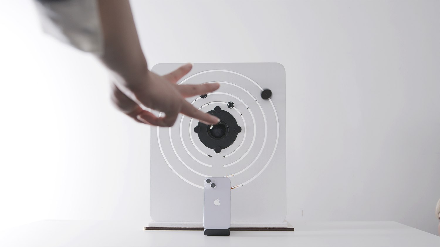
Each gesture, held in front of the device, moves its own ring.
Demonstrated
The five clips below are the sequence in order, shown and tested with people who had never used the device before.
Each gesture unlocks one layer. The first gesture, held at its angle, releases the first lock; the second releases the second, and so on through the fourth. The fifth gesture, the open palm, commits the sequence: the iris rotates open, the push rod extends, and the ball drops out. Nothing happens at all until every layer before it has been cleared, so a wrong angle anywhere in the chain simply leaves the mechanism where it was.